Scantool.net OBDII interface circuit and OBDII connector/cable
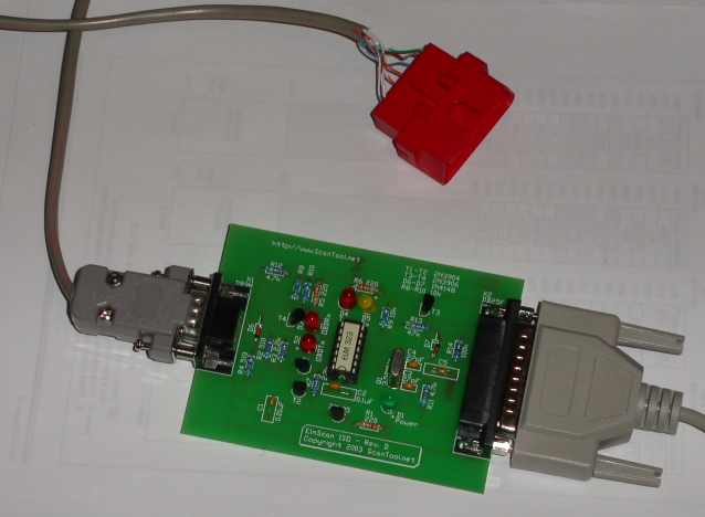
Received all the parts to assemble a scantool OBDII interface circuit. This is the same circuit that www.scantool.net sells and also the same example circuit listed in the ELM323 datasheet. In fact, I bought the PCB and ELM323 from www.scantool.net and just assembled it all myself with components I got from Digi-Key.
We decided to try to make our own OBDII interface cables since the cheapest ones we could find to buy were ~25/ea!!! We obtained some OBDII shells and terminals from Power and Signal Group and will need to assemble our own cables. Power and Signal was the only place I could find that sold these OBDII connector parts and they were a big hassle to order. Power and Signal does not generally deal with small orders like the one I made. The part numbers you need are 12110252 shell, 12047581 pins, 12110254 locking clip. Many of these have minimum orders (I had to order enough to make about 20 connectors) and they only ship C.O.D. unless you have an account. So, overall this will be more expexpensive than buying 1-2 prebuilt cables, but where's the fun in that? However, since we could build 20 cables, it will effectively be much cheaper this way (even though we'll only need a couple). And we'll have enough extra connectors to make 20 of these projects for friends and enemies! Next step is to assemble an OBDII interface cable to connect to the scantool circuit and test out the ELM323 chip and circuit. Scantool.net offers free software to use with this circuit, so that's what I plan to use to test it. It's been brought to my attention that Multiplex Engineering also sells OBDII cables and individual connectors, terminals and shells. While more expensive, per unit, than Power and Signal, they may be good if you just want a few connectors.
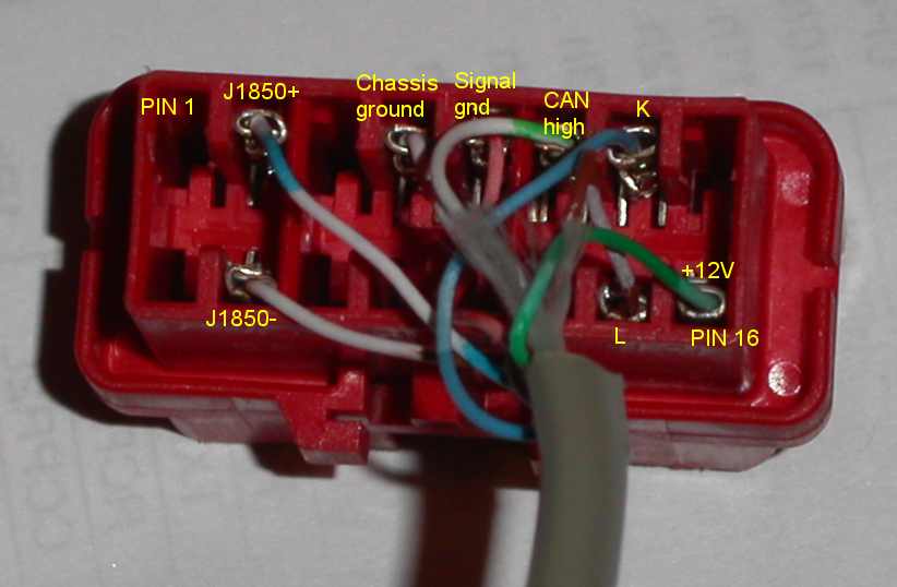
You can see the connectors and terminals in the pictures below. The scantool circuit only requires four connections (K, L, signal gnd & 12v) to the OBDII interface, but since I had 8 wires in the cable, I decided to hook the other four up to some other signals. The J1850+ and J1850- pins are used in the VPW and PWM protocol interfaces (as compared to the ISO-9141 that I'm designing around). Elm Electronics also sells interface chips for those protocols, so in the future if I want to add on the ability to interface to an auto that uses the VPW or PWM protocol, I've already got a cable I can use. The CAN high (J2284) signal (and unconnected CAN low signal at pin 14) are used in a fourth type of OBDII protocol.